By the numbers
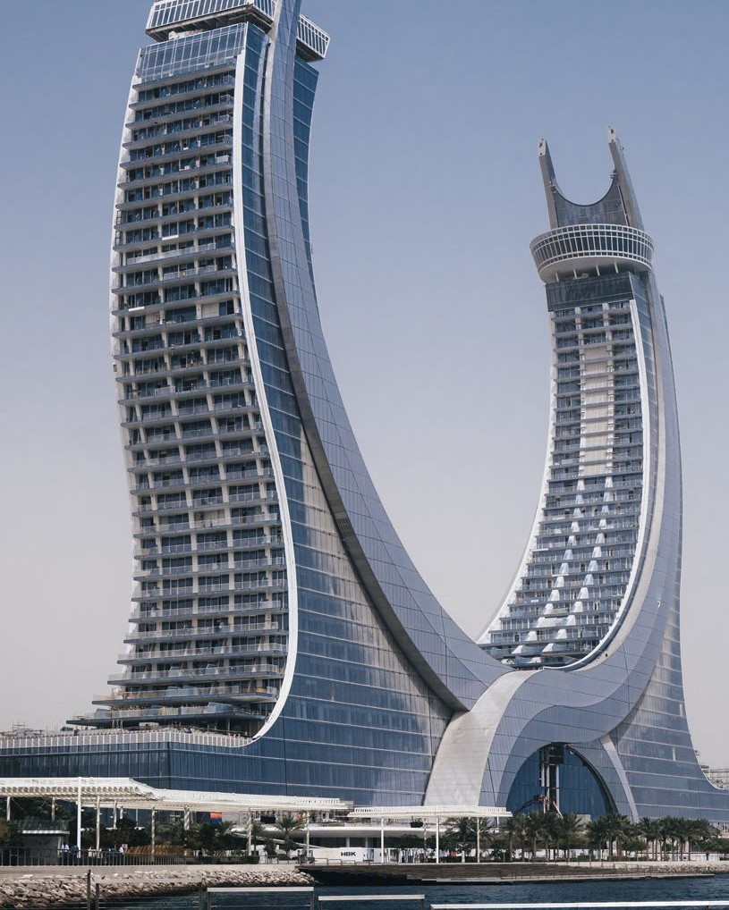
Twin crescents, 211 metres tall, 36 floors each.
The structural skeleton answers a unique loading problem — each tower curves in two
planes simultaneously, so floor plates rotate as they rise and lateral loads stack
asymmetrically against the wind.
- Crown height211 m
- Floors per tower36
- Total floor area300,000 m²
- Hotel rooms & suites500+
- Restaurants & bars18
- Spire structureStainless steel finial
Material specification
S460 high-strength frame, fire-protected, with marine-grade finish.
At this height and footprint, the lateral system carries far more load than gravity. We
engineered the primary frame in S460 NL plate — higher yield, less section, less weight
on the foundations.
- Primary frameS460 NL plate columns
- Floor structureS355 + composite deck
- Fire protectionIntumescent · 90 min rating
- Curtain wallUnitised glass façade
- Fabrication classEN 1090 EXC4
- Weld procedureAWS D1.1 + ISO 3834-2
The challenge
A crescent geometry that twists in two planes as it rises.
Most tall buildings stack identical floor plates and let the structure repeat. Katara doesn't.
Each floor plate is a slightly different shape — rotated, scaled, offset — because
the silhouette has to read as a continuous crescent from any approach.
Practically, that meant no two columns were exactly alike, no two floor beams identical, and
every connection was a one-off. Standard fabrication economics didn't apply.
The solution
Parametric detailing, automated cutting, and a discipline-led erection sequence.
We modelled every column and every beam as a parametric instance — same family,
different angles — then drove our CNC plasma and beam-saw cells directly from the BIM
output. No drawings on the shop floor; the steel knew its own geometry.
On site, the towers were lifted floor by floor, with a real-time survey loop that fed
measured deflections back into the next floor's setting-out. Final crown verticality
measured under 1/4000 — well inside the 1/2000 spec.